Design A 3:8 Decoder Circuit Using Gates
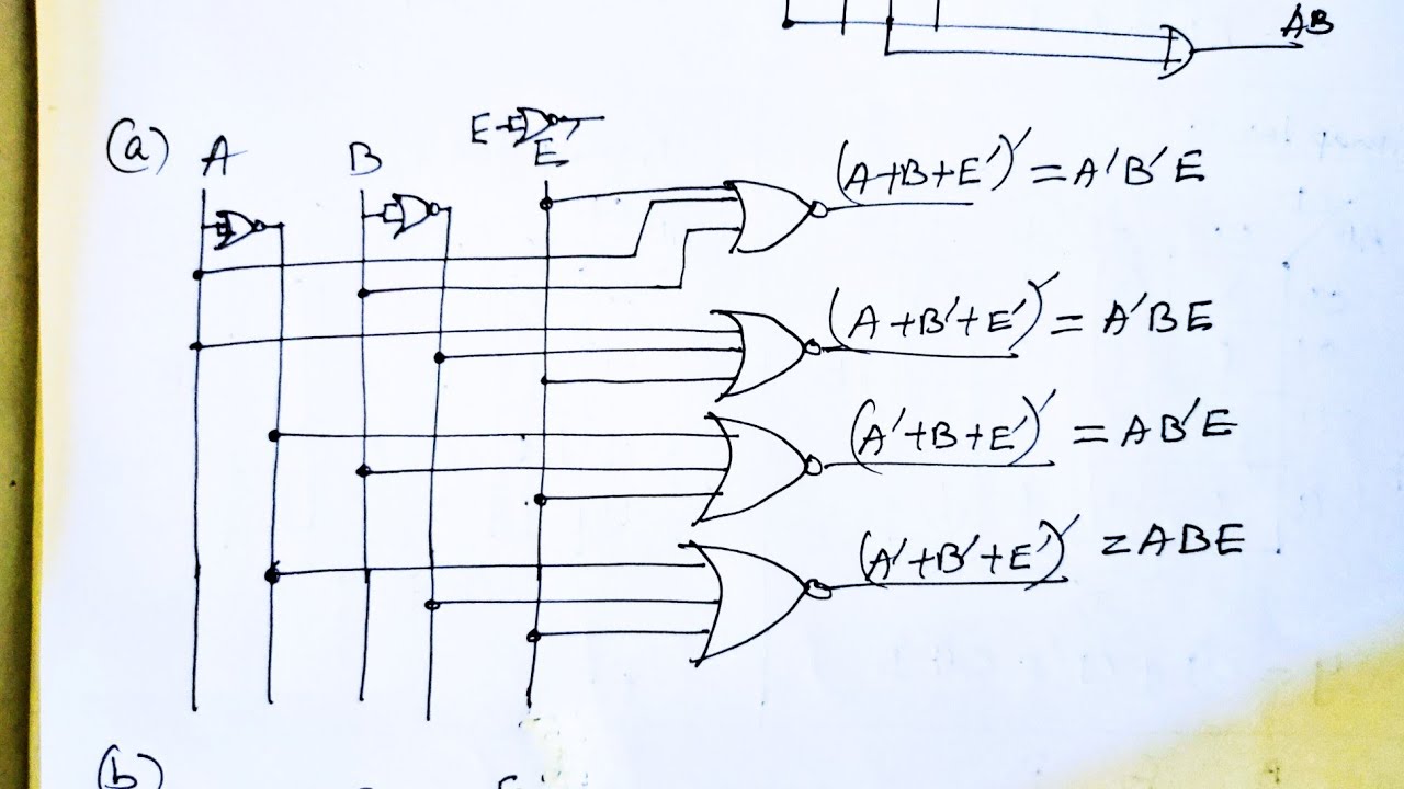
Design full adder circuit using decoder and multiplexer Decoder vhdl encoder using 3x8 8x3 ckt write engineersgarage Design full adder using 3:8 decoder with active low outputs and nand gates.
3 To 8 Decoder Schematic
8 bit decoder circuit Decoder adder using full circuit active low nand gates outputs logical comment add link Design a full adder circuit using decoder and multiplexer
Encoder and decoder circuit diagram
Decoder, 3 to 8 decoder block diagram, truth table, and logic diagramSeven segment display decoder 3 to 8 decoder schematic3 to 8 decoder.
More combinational circuitsBuilding 3-8 decoder with two 2-4 decoders and a few additional gates 3 to 8 decoder logic diagram3 to 8 decoder logic diagram.

Decoder using decoders only logic three implementation digital do stack
4 to 16 decoder circuit diagram3 to 8 decoder circuit diagram Bcd to 7 segment decoder circuit diagramVhdl tutorial 13: design 3×8 decoder and 8×3 encoder using vhdl.
Decoder decoders using two gates schematic enable circuit additional few building electrical engineering circuitlab createdDigital logic 3 to 8 decoder circuit diagram and truth tableImplement full adder using 3 to 8 decoder and nand gates.

Digital logic
Design a 3:8 decoder circuit using gatesDecoder functions showing three circuit logic digital did 2:4 decoder circuit diagramBlock diagram of encoder and decoder.
Adder decoder full combinational gate htm activeSeven segment display circuit diagram 3 to 8 decoder schematicCircuit diagram of 3 8 decoder.

4 to 16 decoder circuit diagram
Logic circuit diagram of full subtractor3 to 8 decoder circuit diagram Design a 1 bit full subtractor using nand gates onlySolved question on vhdl to decoder using two to chegg 0.
Draw circuit using only nand gates[diagram] relay logic diagram Implementation of full adder using mux.


Design full adder using 3:8 decoder with active low outputs and NAND gates.
Draw Circuit Using Only Nand Gates

3 To 8 Decoder Schematic

3 to 8 decoder logic diagram - Wiring Diagram and Schematics

2:4 Decoder Circuit Diagram

3 To 8 Decoder Schematic

Logic Circuit Diagram Of Full Subtractor

8 Bit Decoder Circuit